
Engineering & Research Portfolio
Vasundhra Arulazi, B.S. Materials Engineering, Purdue University (expected May 2029). Interests: high-temperature and aerospace materials, thermal protection systems.
Torch igniterBiVO₄ gas sensorLinkedInContact
GOx/GH₂ Torch Igniter
Purdue Undergraduate Rocket Propulsion Lab | Sep 2025 – present
| Role | CAD and manufacturing (team of 3) |
| Tools | Fusion 360 CAD/CAM, HAAS VF-4 mill, HAAS UMC 5-axis mill, Renishaw OMP40-2 probe |
| Hardware | GOx/GH₂ torch igniter, 316L stainless, additively manufactured + post-machined |
| Status | Seal and spark plug features machined; port program approved for the UMC (Sep 2026); hot-fire targeted Dec 2026 |
Requirement set from the PURPL Torch Training Program: an igniter that can be printed in metal, survives 1 s of steady-state operation, tolerates heat soak into the body before, during, and after the burn, and runs on the existing test stand’s propellants and flow rates.
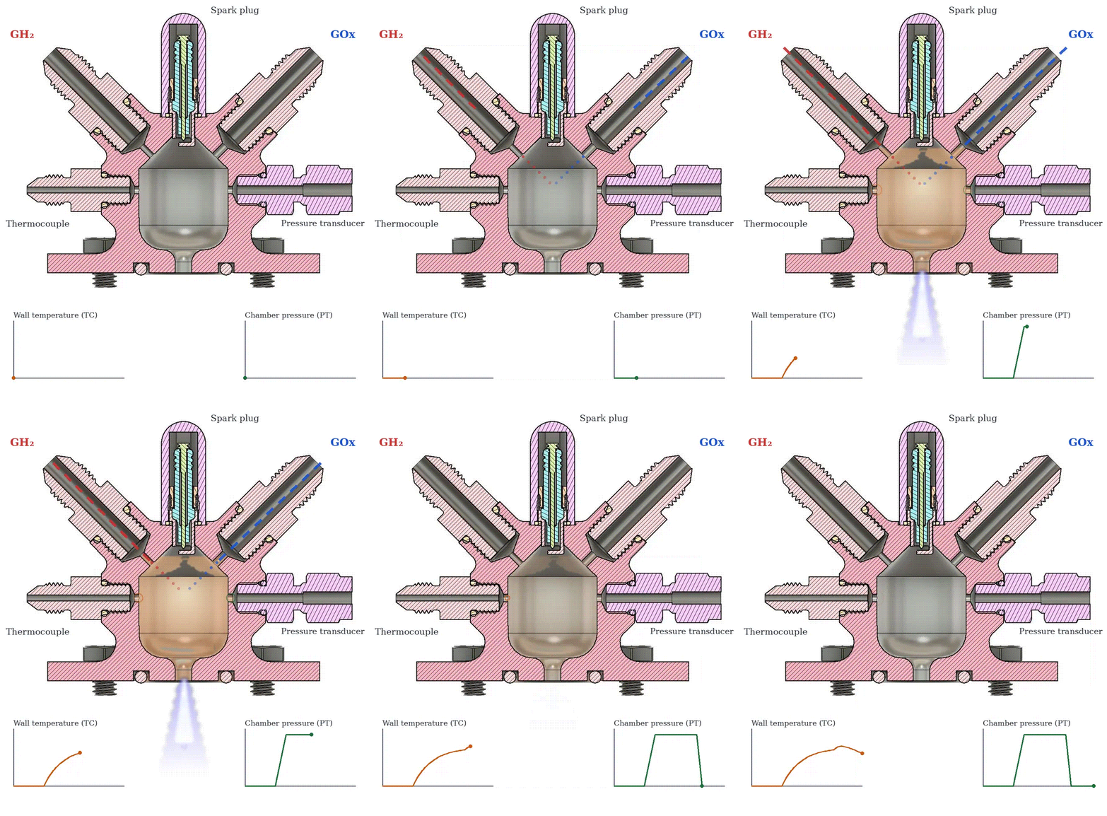
Figure 1. Section view: GH₂ (left) and GOx (right) enter through the angled ports, the spark plug fires on the axis, and the thermocouple (left) and pressure transducer (right) sit on the horizontal ports. Animation and traces are illustrative, not simulation or test data.

Figure 2. As-printed 316L body, before machining.
Design point
Table 1. Design point from the team design review, Dec 2025.
| Parameter | Value | Parameter | Value |
|---|---|---|---|
| Propellants | GOx / GH₂ | O/F (mass) | 2 : 1 |
| Chamber pressure | 130.3 psig | Chamber temp. | ≈ 2153 K |
| Thrust | 2.25 lbf | Specific impulse | 146.5 s |
| Ox flow | 0.0117 lbm/s | Fuel flow | 0.00595 lbm/s |
| Ox feed pressure | 237.2 psig | Fuel feed pressure | 240.2 psig |
| Ox injection area | 0.002 in² | Fuel injection area | 0.005 in² |
Team design review, Dec 2025. Combustion temperature for GOx/GH₂ peaks near 3400 K around O/F ≈ 8; running fuel-rich at O/F 2 holds the flame near 2150 K, which keeps the thermal load on the 316L body manageable for a 1 s burn.
Structural margins
Table 2. Structural hand calculations.
| Check | Load case | Allowable | Stress | FoS |
|---|---|---|---|---|
| Flange bolts, 4 × ¼-20 (316L) | 500 psi on 1.875 in² wetted area, 234 lbf/bolt | 30.0 ksi yield | 8.37 ksi | 3.58 |
| Chamber wall, thick-wall hoop | 500 psi, a = 0.459 in, b = 0.645 in, wall at 1076.5 K | 15.95 ksi yield at temp. | 1.53 ksi | 10.45 |
Hand calcs from the design review. Elevated-temperature yield from Nickel Institute data for 316L; wall temperature taken as half the predicted flame temperature.
Interfaces
| Propellant ports | Two angled impinging ports: GH₂ (left), GOx (right) |
| Thermocouple port (left) | Parker Triple-Lok 37° flare (JIC) |
| Pressure transducer port (right) | Swagelok flared fitting |
| Igniter | Spark plug, ¼-32 UNEF thread |
| Stand seal | FKM O-ring, AS568 size 2-210, face seal |
| Hardware cost | $107.85 total bill of materials |
Failure modes considered
Table 3. Failure modes and effects.
| Mode | Cause | Mitigation |
|---|---|---|
| Throat erosion | Local melting of 316L at the throat | Burn limited to 1 s |
| External leak | Seal/fitting damage, thermal-stress cracking | Rated fittings, controlled installation |
| Chamber rupture | Overpressure, material stress | Margin above (FoS ≥ 3.5), 1 s burn |
Timeline
Design
Three-person team in the PURPL Torch Training Program. I owned the CAD: chamber, angled impinging ports for GH₂ and GOx, thermocouple and pressure transducer ports, spark plug boss, and a bolted flange with a 2-210 face seal, all sized for off-the-shelf JIC and Swagelok fittings. We presented the design review on Dec 4, 2025.
The body went out to a vendor and came back printed in 316L. As-printed surfaces can’t seal or hold a thread, so every interface still had to be finished on a mill, and I took on writing the CAM for all of it.
First machining on the VF-4
Spark plug bore (program approved Mar 11) and seal/flange features (approved Apr 14). This is where workholding bit us: the part sat in 3D-printed PLA soft jaws at 50% infill, which couldn’t clamp stainless rigidly. I cut the seal features with a 1/8″ ball end mill at low forces and set offsets by probing the part instead of trusting the stock position. We ended up hand-tapping the ¼-32 UNEF spark plug thread instead of thread-milling it.
Moving the ports to the UMC
The ports need real feeds and speeds in 316L, and PLA jaws weren’t going to survive that. I reprogrammed the four ports for the HAAS UMC 5-axis: probe, ramp in with a 1/4″ ball end mill, then thread-mill each port. Approved Sep 26. I also started as a peer mentor for the program this fall.
Hot-fire (planned)
Finish the port setup and hot-fire on the PURPL stand.
Manufacturing details
Table 4. Machining setups. Cycle times are Fusion 360 CAM estimates.
| Setup | Machine | Features | Operations | Est. cycle |
|---|---|---|---|---|
| 1. Flange & seal | HAAS VF-4 | O-ring seal features, flange bolt holes | Probe Z/XY, 2 bore ops | 1 min 52 s |
| 2. Spark plug boss | HAAS VF-4 | Bore for ¼-32 UNEF spark plug | Bore; thread hand-tapped | 1 min 32 s (bore) |
| 3. Ports | HAAS UMC 5-axis | GOx/GH₂ ports (3/8 thread mill), TC/PT ports (1/4 thread mill) | 2 probe, 4 ramp, 4 thread-mill ops | 3 min 48 s |
Setups 1–2 are complete. Setup 3 moved to the UMC 5-axis (see timeline). Tooling: Kennametal HARVI end mills, Lakeshore Carbide single-profile thread mills (3/8 for propellant ports, 1/4 for TC/PT ports), Renishaw OMP40-2 probe, flood coolant.
Mo-doped BiVO₄ Thin-Film Ammonia Sensor
Independent research with Prof. S. Kalainathan (VIT) | Jul 2023 – Jun 2024
| Role | I did characterization, gas sensing, and wrote the original draft of the paper |
| Methods | XRD (Bruker D8 Discover), SEM (Thermo Fisher Prisma), 3D digital microscopy (Olympus DSX1000), gas sensing with a Keithley 6517B electrometer |
| Result | Response to 50 ppm NH₃ at 27 °C: 149 (5% Mo) vs. 16.3 (undoped) |
| Output | J. Mater. Sci.: Mater. Electron. 35, 347 (2024); 2nd, Science & Engineering Fair of Houston; 3rd, Texas Science & Engineering Fair |
Question: can Mo doping make a BiVO₄ thin film detect ammonia at room temperature? OSHA’s workplace limit for NH₃ is 50 ppm, and most metal-oxide sensors need a heater to respond. Films of Bi₁₋ₓMoₓVO₄ (x = 0, 0.01, 0.03, 0.05) were spray-pyrolyzed onto glass at 200 °C by my advisor’s lab at VIT. I characterized them and ran the sensing tests.
Timeline
Start
Started as a high school student working with Prof. Kalainathan’s group at VIT, which deposited the four film compositions.
Characterization and sensing
SEM and 3D digital microscopy at Houston Electron Microscopy; 2D-XRD at the University of Houston (frames collected Nov 21, 2023). Built out the ammonia response data from 10 to 50 ppm and the selectivity, stability, and humidity tests.
Paper
Wrote the original draft. Submitted Dec 13, accepted Jan 26, published Feb 17, 2024 in J. Mater. Sci.: Mater. Electron.
Science fairs
2nd place at the Science and Engineering Fair of Houston, 3rd place at the Texas Science and Engineering Fair.
Structure (XRD)
All films index to monoclinic scheelite BiVO₄ (JCPDS 14-0688) with no Bi, V, or Mo oxide secondary phases. The (121) peak shifts to lower 2θ as Mo increases, consistent with lattice expansion from substitution. Crystallite size from Scherrer (K = 0.9, λ = 1.54 Å).
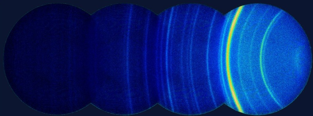
Figure 3. 2D-XRD detector frames of a Mo-doped film, 240 s per frame. Each arc is a set of diffracting planes.
Table 5. Lattice parameters and XRD-derived microstructure.
| Film | a (Å) | Cell vol. (ų) | Crystallite (nm) | Microstrain (×10⁻⁵) | Dislocation density (m⁻²) |
|---|---|---|---|---|---|
| Undoped | 5.11 | 307 | 162 | 3.77 | 4 × 10¹³ |
| 1% Mo | 5.12 | 308 | 157 | 4.00 | 4 × 10¹³ |
| 3% Mo | 5.13 | 309 | 155 | 4.12 | 4 × 10¹³ |
| 5% Mo | 5.14 | 311 | 146 | 4.66 | 5 × 10¹³ |
Morphology (SEM)

150×

500×

1500×
Figure 4. Undoped BiVO₄ film at 150×, 500×, and 1500×, showing the coral-like surface and open pores. Backscatter SEM, 20 kV, Houston Electron Microscopy.
Gas-sensing setup
| Chamber | 1 L, static; target gas volume set by static liquid–gas distribution |
| Electronics | Keithley 6517B electrometer, GPIB data logging |
| Sample | 1.5 × 1 cm film, Ag paste + Cu wire ohmic contacts |
| Conditions | 27 °C, 10–50 ppm NH₃ |
| Metrics | Response S = Igas / Iair; response time to 90%, recovery to 10% of baseline |
Results
Table 6. Sensor response S versus NH₃ concentration, 27 °C.
| Film | 10 ppm | 20 ppm | 30 ppm | 40 ppm | 50 ppm | tresp / trec at 50 ppm |
|---|---|---|---|---|---|---|
| Undoped | 1.91 | 3.33 | 5.13 | 8.25 | 16.33 | 408 s / 190 s |
| 1% Mo | 2.19 | 3.56 | 7.05 | 11.7 | 21.42 | 350 s / 152 s |
| 3% Mo | 3.99 | 5.53 | 10.0 | 14.3 | 23.0 | 336 s / 138 s |
| 5% Mo | 27 | 51 | 73.95 | 115 | 149 | 339 s / 127 s |
Table 7. Selectivity of the 5% Mo film.
| Gas (50 ppm) | Ammonia | Xylene | Butanol | Ethanol | Acetone | 2-Propanol |
|---|---|---|---|---|---|---|
| Response S | 149 | 9.93 | 5.68 | 2.44 | 1.82 | 1.27 |
| Repeatability | 4 consecutive cycles at 10 ppm, same response |
| Stability | Response unchanged after 2 weeks |
| Humidity | Response within ±3 over 10–90% RH at 10 ppm |
Interpretation
Response tracks Mo content with smaller crystallites, higher microstrain, higher dislocation density, and more porous morphology. I attributed the ~9× gain mainly to solute-induced lattice strain and defect density, not surface area alone. Mechanism: O₂⁻ adsorbed on the n-type surface traps electrons; NH₃ reacts with it (4NH₃ + 3O₂⁻ → 2N₂ + 6H₂O + 6e⁻), releasing electrons back and raising conductance.